CHILD SAFETYWEARABLE DEVICE
INTRODUCTION
Nowadays crimes against and accidents occurring to kids are increasing
rapidly. So there should be strict monitoring by parents. Parents should be aware
of their kids. Hence for this purpose we are introducing a CHILD SAFETY
WEARABLE DEVICE . Nowadays working mothers send their kids to nurseries
or kinder gardens and schools on their working days. The motivation for this
wearable comes from the increasing need for safety for little children in current
times as there could be scenarios of the child getting lost in the major crowded
areas.In increasing crimes or accidents on kids, parents need to consider the way
to protect them and predict what are going to happen to them to know their habits
of ordinary behaviours or related people around them. Most of the wearables
available today are focused on providing the location and activity of the child to
the parents via Wi-Fi and Bluetooth.

In many cities,working mothers’ kids are being taken care by nurseries or
kindergardens on their working days. They spend less than 3-4 hours with their
kids. Kids under the age of 6, they are developing physically faster but sometimes
cannot describe their emotions by words to their parents even though those were
scary, happy, surprise or sad. But the responsibility of kids’ security is on their
own parents wherever, whenever or whatever.
The platform on which this project will be running on is the Arduino Uno
microcontroller board based on the ATmega328P, and the functions of sending
and receiving SMS and connecting to the internet, which is provided by the
Arduino GSM shield using the GSM network. Also, additional modules employed
which will provide the current location of the child to the parents via SMS. The
wearable comes equipped with a distress alarm buzzer which sets to active by
sending the SMS keyword “BUZ” to the wearable. Since, the buzzer is loud and
can be heard by the surrounding crowd from very considerable distance. Also the
parents via SMS can receive accurate coordinates of the child, which can help
them to locate the child with pinpoint accuracy. For surveillance of the child’s
surroundings, to get a clearer picture of the location, this wearable contain a GSM
module incorporated in it. The major focus of this wearable project is the GSM
module which is a better alternative than Bluetooth. GSM is an open, digital
cellular technology used for transmitting mobile voice and data services. It is used
to send messages to the concerned authority in case of any kind of misconduct
taking place.
The wearable device, for now, is not built on a SoC model, rather has
been proposed using larger components and can later build on the SoC platform
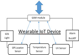
once put into manufacture. The wearable IoT device tasked with acquiring various
data from the all the different modules connected. It comprises of Arduino Uno
based on the ATmega328P microcontroller. It receives the data from its various
physically connected modules, anatomizes this data and refines the data in a more
user understandable format to the different available user interfaces. The user,
therefore, can conveniently view the information on the cellphone.
The physical characteristics of the wearable device are proposed to be as a
wrist watch which remains placed around the wrist of the child during times when
the child is not being accompanied by an adult/parent. For the moment the design
is not made compact, since the main focus now has been to show that this concept
of smart wearables would be highly impactful for the safety of children. The
wearable system runs on a power supply of 5V. In order to maximize power
consumption, the wearable device has been programmed to provide GPS and
image information only upon request by SMS text via GSM shield.
LITERATURE SURVEY
International Journal of Management and Social Sciences Research (IJMSSR)
ISSN: 2319-4421 Volume 6, No. 8, August 2017 [1]
In a contemporary family setup, when both parents are working, it
becomes difficult for them to accompany their child wherever they go. But with
advances in internet and mobile applications there are many smart devices
introduced in the market which enables parents to track their kids and ensure their
safety. Therefore a survey was conducted on 110 parents of south Bangalore who
purchased a smart wearable device (Smart watch) for their kids. It was found that
most of the parents are happy with this device and they feel it can lead to a safer
community.
The concept of a smart wearable device for little children,the major
advantage of this wearable device over other
is that it can be used in any
cellphone and doesn’t necessarily require an expensive smartphone and not a very
tech savvy individual to operate. SMS text enabled communication medium
between the child’s wearable and the parent as the environment for GSM mobile
communication is almost present everywhere. It will also provide the surrounding
temperature and the UV radiation index so that the parent can keep track if the
temperature or UV radiation is not suitable for the child.
This study was intended to find out the perception of parents on future
wearable technology (Smart watch). The survey was conducted through closed
end questionnaire on parents who purchased smart wearable device for kids.
Around 200 respondents were selected randomly, from south Bangalore and
further filtered down to 110 sample size.
PROPOSED SYSTEM
This project is based on the concept of a smart wearable device for children. The
purpose of this device is to help parents to locate their children with ease. At the
moment there are many wearable device in the market which helps to track the
daily activities of children and also help to find the child using bluetooth service
present on the device. But bluetooth alone become unreliable medium of
communication between parent and child. So our focus is to have an SMS text
enabled communication medium between child’s wearable and parent as an
environment for GSM mobile communication as present everywhere. We are
connecting microcontroller to internet by adding Wi-Fi module by which the data
are uploaded to the server. The live location is tracked into the server and parent
can access it through the mobile app. Also a boundary is decided, that is if the
child moves beyond the pre-defined area an alert message will be send to parent’s
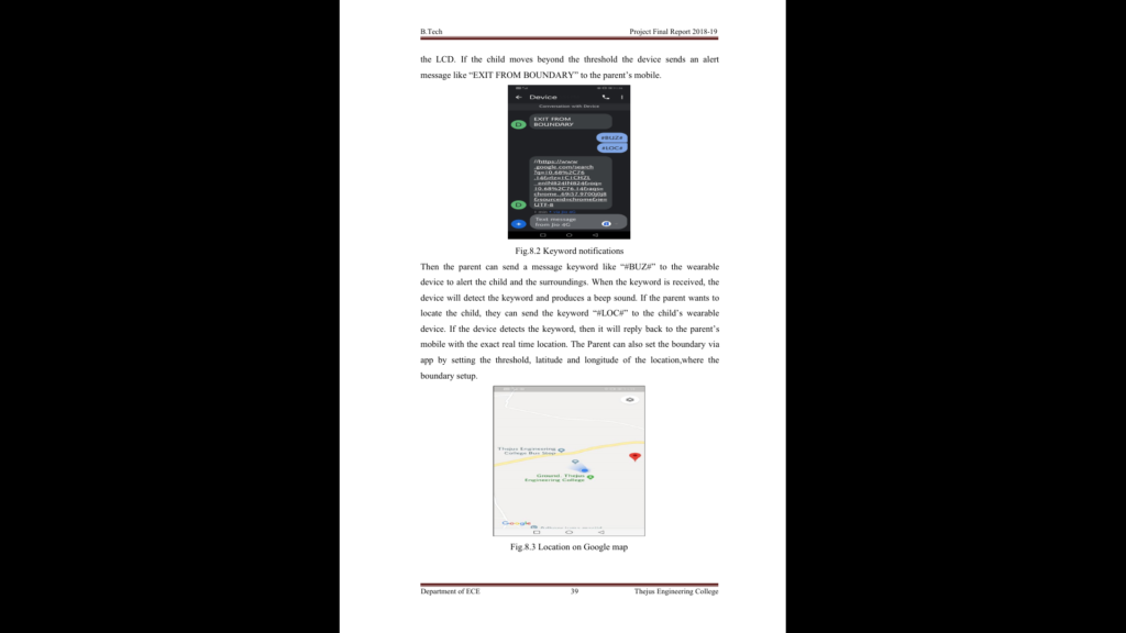
android app. Then parent can send a keyword like “#BUZ#” to the wearable
device so that a distress alarm buzzer will be enabled and produces a sound, in
order to get the attention of surrounding people. When the alert message is
received, then parent can check the location of the child by sending a keyword
“#LOC#” to the wearable. If the keyword is received to the device, then the device
will send the real-time location of the child to the parent. They can track the
location by tapping on the link which is received from the device. If any trouble is
found, then parent can send help message to the school faculties and nearby police
station to secure the child from serious issues. Thus by this device, parents can
ensure the safety of their child.
COMPONENTS REQUIRED
5.1 GPS MODULE
GPS stands for “Global Positioning System” . It is a satellite navigation
system used to determine the ground position of an object. A GPS receiver
combines the broadcasts from multiple satellites to calculate its exact position
using a process called triangulation. The orbits are designed so that there are
always 6 satellites in view, from most places on the earth. GPS uses a lot of
complex technology, but the concept is simple. The GPS receiver gets a signal
from each GPS satellite. The satellites transmit the exact time the signals are sent.
GPS does not require the user to transmit any data, and it operates
independently of any telephonic or internet reception, though these technologies
can enhance the usefulness of the GPS positioning information. The GPS provides
critical positioning capabilities to military, civil, and commercial users around the
world. The United States government created the system, maintains it, and makes
it freely accessible to anyone with a GPS receiver.
The navigational signals transmitted by GPS satellites encode a variety
of information including satellite positions, the state of the internal clocks, and the
health of the network. These signals are transmitted on two separate carrier
frequencies that are common to all satellites in the network. Two different
encodings are used: a public encoding that enables lower resolution navigation,
and an encrypted encoding used by the U.S. military.
5.2 ARDUINO UNO
The Arduino UNO is an open-source microcontroller board based on
the MicrochipATmega328P microcontroller and developed by Arduino.cc. The
board is equipped with sets of digital and analog input/output (I/O) pins that may
be interfaced to various expansion boards (shields) and other circuits.
The ATmega328 is a single-chipmicrocontroller created by Atmel in
the megaAVR family (later Microchip Technology acquired Atmel in 2016). It
has a modified Harvard architecture8-bitRISC processor core. It has 20 digital
input/ output pins (6 can be used as analoginputs ), a 16 MHz resonator , a USB
connection, a power jack , an ICSP header and a reset button. Arduino consists of
both a physical programmable circuit board (often referred to as microcontroller),
and a piece of software or IDE (integrated development environment ) that runs
on a computer, used to write and upload computer code to the physical board.
5.3 GSM MODULE
Fig. 5.3 GSM module
GSM stands for “Global System for Mobile communication” , is an
architecture used for mobile communication in most of the countries. GSM/GPRS
module is used to establish communication between a computer and a GSM
system.
It can perform functions like receive, send or delete sms messages in a
SIM ,read, add, search phonebook entries of the SIM and make, receive or reject a
voice call. GSM was intended to be a secure wireless system. It has considered
the user authentication using a pre-shared key and challenge-response, and over-
the-air encryption.
Features:
- Dual-band 900/1800 MHz
- GPRS multi-slot class 10/8GPRS mobile station class B
- Complaint to GSM phase 2/2+class 4,Control via AT commands(GSM
07.07,07.05 SIMCOM
enhanced AT commands) - Low power consumption: 1.5mA(sleep mode)
- Operation temperature :-40oC to +85oC
- Status indicator (D5) : it will flash continuously whenever the call arrives
otherwise it is left ON - Network LED(D6): this led will blink every second which indicates that the
GSM module is not connected to the mobile network. Once the connection is
established successfully ,the led will blink continuously every 3 seconds.
Booting the GSM module:
1.Insert the SIM card to the GSM module and lock it.
2.Connect the adapter to the GSM module and turn it ON.
3.Now wait for some time and see the blinking rate of ‘status
LED’ or
‘network LED’( GSM module will take some time to establish connection
with the mobile network).
4.Once the connection is established successfully, the status/network LED will
blink continuously every 3 seconds. You may try making a call to the mobile
number of the sim card inside GSM module. If you hear a ring back ,the GSM
module has successfully established network connection.
5.6 ALARM
A buzzer or beeper is an audio signalling device, which may be mechanical, or
electromechanical. Typical uses of buzzers and beepers include alarm devices and
timers. Alarm gives an audible, visual or other form of alarm signal about a
problem or condition. Alarm systems are often outfitted with a siren. While
technological advancements have caused buzzers to be impractical and
undesirable, there are still instances in which buzzers and similar circuits may be
used. Present day applications include: Novelty uses, Judging panels, Educational
purposes, Annunciator panels, Electronic metronomes, Game showlock-out device
etc.
6.1 ALGORITHM
Step 1: Begin
Step 2: Run search for device
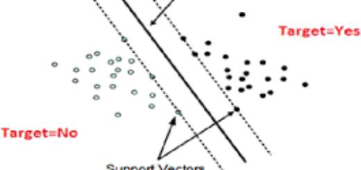
Step 3: If device found ==“ YES” start communication between app and device.
Step 4: If device found == “NO” ,“ No Data available”
Step 5: If communication is started between app and device, a boundary is set and
run search for successful connection.
Step 6: If successful connection == “YES” ,Get the position from GPS sensor
Step 7: If device exit from boundary set ==“YES” an alert is send to user.
Step 8: If device exit from boundary set == “ NO” , Send keywords
Step 9: Information is displayed to the user.
Step 10: Stop
6.3 ARDUINO IDE
The Arduino integrated development environment (IDE) is a cross-
platform application that is written in the programming language Java. It is used to
write and upload programs to Arduino board.
The source code for the IDE is released under the (GNU) General Public
License, version 2. The Arduino IDE supports the languages C and C++ using
special rules of code structuring. The Arduino IDE supplies a software library
from the Wiring project, which provides many common input and output
procedures.
Step 1
First we must have our ESP8266 and a USB cable connected to the
programming device.
Step 2
Download Arduino IDE Software. We can get different versions of
Arduino IDE from the Download page on the Arduino Official website. We must
select were software, which is compatible with which operating system (Windows,
IOS, or Linux). After the file download is complete, unzip the file.
Step 3
Power up the ESP board. Connect the ESP board to wer computer using
the USB cable.
Step 4
Launch Arduino IDE.After our Arduino IDE software is downloaded, we
need to unzip the folder. Inside the folder, we can find the application icon with an
infinity label (application.exe). Double-click the icon to start the IDE
Step 5
Open our first project.
Once the software starts, we have two options
- Create a new project
- Open an existing project example.
To create a new project, select File → New.
Step 6
Select our NodeMCU.1.0 board. To avoid any error while uploading
program to the board, we must select the correct Arduino board name, which
matches with the board connected to computer. Go to Tools → Board and select
board.
Step 7
Select serial port as COM4.
Step 8
Upload the program to board. Before explaining how we can upload our
program to the board, we must demonstrate the function of each symbol appearing
in the Arduino IDE toolbar.
A − Used to check if there is any compilation error.
B − Used to upload a program to the Arduino board.
C − Shortcut used to create a new sketch.
D − Used to directly open one of the example sketch.
E − Used to save sketch.
F − Serial monitor used to receive serial data from the board and send the serial
data to the board.
Now, simply click the “Upload” button in the environment. Wait a few
seconds; we will see the RX and TX LEDs on the board, flashing. If the upload is
successful, the message “Done uploading” will appear in the status bac
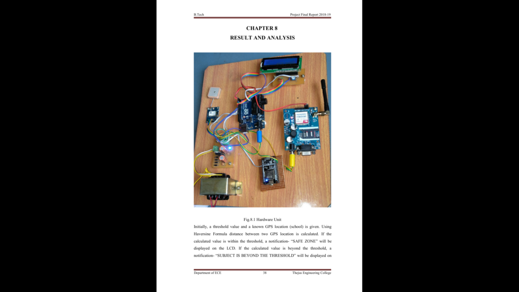
Initially, a threshold value and a known GPS location (school) is given. Using
Haversine Formula distance between two GPS location is calculated. If the
calculated value is within the threshold, a notification- “SAFE ZONE” will be
displayed on the LCD. If the calculated value is beyond the threshold, a
notification- “SUBJECT IS BEYOND THE THRESHOLD” will be displayed on
the LCD. If the child moves beyond the threshold the device sends an alert
message like “EXIT FROM BOUNDARY” to the parent’s mobile.
ADVANTAGES
User friendly
User-friendly describes a hardware device or software interface that is easy
to use. It is “friendly” to the user. Meaning it is not difficult to learn or
understand. While “user -friendly” is a subjective term.
Faster Responsivity
It provides faster response time because it is very easy to send help
messages to the police station by pressing a single button.
Efficient real time monitoring
It provides exact real time location of the person using GPS module. So we
can monitor them efficiently.
Simple
It is not overly complex, but instead is straight forward, providing quick
access to common features or commands.
Accurate GPS location
Easy to use
Feasible Cost
Reliable
CONCLUSION
The child safety wearable device is capable of acting as a smart device. In
this current scenario, as the crimes and accidents are more against children. There
is necessity for parents to monitor their kids. So our project aims at providing
parents with the real-time location, along with Distress alarm buzzer for alerting
the child and the surroundings. Arduino which can be sewed into fabrics. The use
of GPS module will help to monitor the exact location of the child. GSM module
enable the communication between parent and the device with proper safety. This
wearable device is user friendly, so they can wear it anytime and anywhere. No
harmful effects are produced by this device. The product is lightweight and
compactable. Thus by this product, parent can identify the exact location and can
communicate with child whenever they want.